|
Carna Version 3.3.3
|
Loading...
Searching...
No Matches
|
Carna Version 3.3.3
|
Defines abstract base class for rendering stages that render volume geometries in the scene. More...
#include <VolumeRenderingStage.h>
 Inheritance diagram for Carna::presets::VolumeRenderingStage: Collaboration diagram for Carna::presets::VolumeRenderingStage:
Public Member Functions | |
| VolumeRenderingStage (unsigned int geometryType) | |
| Instantiates. The created stage will render such base::Geometry scene graph nodes, whose geometry types equal geometryType. | |
| virtual | ~VolumeRenderingStage () |
| Deletes. | |
| void | setSampleRate (unsigned int sampleRate) |
| Sets number of slices to be rendered per segment. | |
| unsigned int | sampleRate () const |
| Tells number of slices to be rendered per segment. | |
| virtual void | renderPass (const base::math::Matrix4f &viewTransform, base::RenderTask &rt, const base::Viewport &vp) override |
| Triggers the volume rendering. | |
| Public Member Functions inherited from Carna::base::GeometryStage< base::Renderable::BackToFront > | |
| GeometryStage (unsigned int geometryType, unsigned int geometryTypeMask=RenderQueue< base::Renderable::BackToFront >::EXACT_MATCH_GEOMETRY_TYPE_MASK) | |
| Instantiates s.t. the predefined rendering queue enqueues such Carna::base::Geometry scene graph nodes, whose geometry type AND-linked with geometryTypeMask equals the geometryType specified here. | |
| virtual | ~GeometryStage () |
| Releases acquired video resources. | |
| virtual void | prepareFrame (Node &root) override |
| Called once before each frame. | |
| std::size_t | renderedPassesCount () const |
| Tells the number of passes rendered so far since the beginning of the current frame. | |
| GeometryFeatureType::ManagedInterface & | videoResource (GeometryFeatureType &geometryFeature) const |
| Interfaces the geometryFeature video resources that were acquired by this rendering stage. | |
| const GeometryFeatureType::ManagedInterface & | videoResource (const GeometryFeatureType &geometryFeature) const |
| Public Member Functions inherited from Carna::base::RenderStage | |
| RenderStage () | |
| Instantiates in enabled-state. | |
| virtual | ~RenderStage () |
| Deletes. | |
| virtual RenderStage * | clone () const =0 |
Returns same RenderStage implementation with same configuration. | |
| void | setViewTransformFixed (bool viewTransformFixed) |
| Sets whether the view transform is pass-invariant for the duration of a single frame. | |
| bool | isViewTransformFixed () const |
| Tells whether the view transform is pass-invariant for the duration of a single frame. | |
| virtual void | reshape (FrameRenderer &fr, unsigned int width, unsigned int height) |
| Orders this stage to reshape its buffers according to the specified dimensions. | |
| bool | isInitialized () const |
| Tells whether this stage is ready for rendering. | |
| bool | isEnabled () const |
| Tells whether this stage is enabled. Disabled stages are not rendered by render tasks. | |
| void | setEnabled (bool) |
| Sets whether this stage is enabled. Disabled stages are not rendered by render tasks. | |
| base::FrameRenderer & | renderer () |
| References the renderer this stage belongs to. | |
| const base::FrameRenderer & | renderer () const |
| void | addRenderStageListener (RenderStageListener &listener) |
| Adds listener to the set of listeners this instance notifies in \(\mathcal O\left(\log n\right)\). | |
| void | removeRenderStageListener (RenderStageListener &listener) |
| Removes listener from the set of listeners this instance notifies in \(\mathcal O\left(\log n\right)\). | |
Static Public Attributes | |
| static const unsigned int | DEFAULT_SAMPLE_RATE = 200 |
| Holds the default number of slices rendered per segment. | |
Protected Member Functions | |
| virtual unsigned int | loadVideoResources () |
| Loads video resources when rendering is triggered for the first time. Override this method if you need any additional resources to be loaded, but always call the base implementation. | |
| virtual void | render (const base::Renderable &) override |
| Renders the renderable. | |
| virtual void | createVolumeSamplers (const std::function< void(unsigned int, base::Sampler *) > ®isterSampler)=0 |
| Creates texture samplers for volume textures and uses registerSampler to assign them to the roles that they should be used with. | |
| virtual const base::ShaderProgram & | acquireShader ()=0 |
| Acquires the shader from the base::ShaderManager, that is to be used for rendering the slices. | |
| virtual const std::string & | uniformName (unsigned int role) const =0 |
| Tells the name of the uniform variable, that the role texture is to be bound to. Use configureShader for custom shader configuration that goes beyond that. | |
| virtual void | configureShader ()=0 |
| Performs custom shader configuration on a per-pass level. | |
| virtual void | configureShader (const base::Renderable &)=0 |
| Performs custom shader configuration on a per-volume level. | |
| Protected Member Functions inherited from Carna::base::GeometryStage< base::Renderable::BackToFront > | |
| void | activateGLContext () const |
| Ensures that the OpenGL context of the hosting Carna::base::FrameRenderer is the current one. | |
| virtual void | buildRenderQueues (Node &root, const math::Matrix4f &viewTransform) |
| Builds the rendering queues of this stage. | |
| virtual void | rewindRenderQueues () |
| Rewinds the rendering queues of this stage. | |
| virtual void | updateRenderQueues (const math::Matrix4f &viewTransform) |
| Recomputes the model-view transforms of the renderables enqueued by this stage. | |
Additional Inherited Members | |
| Public Attributes inherited from Carna::base::GeometryStage< base::Renderable::BackToFront > | |
| const unsigned int | geometryType |
| Renders such geometries whose type AND-linked with geometryTypeMask equals this. | |
| const unsigned int | geometryTypeMask |
| Renders such geometries whose type AND-linked with this equals geometryType. | |
| Protected Attributes inherited from Carna::base::GeometryStage< base::Renderable::BackToFront > | |
| RenderQueue< base::Renderable::BackToFront > | rq |
| Holds the predefined rendering queue of this rendering stage. | |
Defines abstract base class for rendering stages that render volume geometries in the scene.
The necessity to evaluate \(f\left(x_i\right)\) for equidistant samples \(x_i\) of a ray, that is shot from each pixel of the screen into the volume geometries of the scene, is common to the typical volume rendering applications like digital radiograph reconstructs, maximum intensity projections or direct volume renderings.
The approach, that probably seems most natural, is the following. By rendering a bounding box around the volume, we would get an invocation of a fragment shader for each such pixel whose ray intersects the volume. The next step would be to somehow obtain the first and last intersection locations \(x_1\) and \(x_n\) respectively within the shader. Finally one would iterate over the equidistant samples \(x_i\) and evaluate them through \(f\).
This actually is a very wide-spread approach to volume rendering, that is called ray marching. It has two disadvantages. First, the looping within the fragment shader comes at the cost of heavy dynamic branching, that slows down the GPU a lot. Second, it requires quite a lot of shader logic to be implemented redundantly for each application. For this two reasons, this class uses a different approach, but one that is certainly inspired by ray marching.
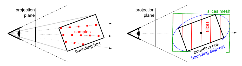
The idea is to use precomputed sample locations. Therefor the samples \(x_i\) of different rays but with same \(i\) are identified as slices. The creation of a mesh that consists of \(n\) slices is easy. The challenge is to position and scale that mesh s.t. it covers the whole volume, i.e. its bounding box like illustrated in the figure above, irrespectively of the view direction. The mesh is oriented s.t. the slices become orthogonal to the viewing direction. It is positioned s.t. its center matches the center of the bounding box. The scaling is a little tricky: We stretch it s.t. it becomes the minimum boundary box to the volume's bounding ellipsoid.
This is an abstract base class for volume rendering stages. The algorithm constructs a sequence of slices. These slices are rendered at the location of every base::Geometry node that this stage processes. The rendering is done s.t. the slices always face exactly towards the camera. Implementations of this class must provide shader that satisfies specific requirements.
It is within the responsibility of this shader to transform the vertices of the slices s.t. they are put in place correctly. Furthermore it is of course the job of the shader to do the texturing of the slices. This abstract class supports the shader in accomplishing both requirements, as explained below.
The vertices of the slices mesh are defined in tangent space coordinates. The z-coordinate is the same for the vertices of a single slice and grows for slices that will be rendered closer to the camera. As usual, rendering requires the transformations of vertices to eye space and beyond. This is done in two steps:
This class computes a matrix that accomplishes the transformation from tangent space to model space. This is pretty easy: The vector of the view direction, transformed to model space by the inverse model-view matrix, is picked as the the normal vector of the tangent space, i.e. the z-component basis vector.
Note that we do not have any requirements upon how the vertices shall be rotated within the plane, the normal vector defines, as long as their rotation is consistent with the texturing. Thus an arbitrary orthogonal vector is constructed, that is taken as the tangent, i.e. the x-component basis vector. The bitangent vector for the y-component is than easily obtained by the cross product of the others two.
The finished tangent-model matrix is uploaded to the shader as an uniform named tangentModel from type mat4.
The volumetric data that is attached to a geometry node is always assumed to be centered within the node. Furthermore the data is scaled s.t. it shapes an unitary cube. This is convenient because OpenGL requires us to specify texture coordinates within \(\left[0, 1\right]^3\). This is why the transformation of model coordinates to texture coordinates requires us to translate the model coordinates by \(\left(0{,}5, 0{,}5, 0{,}5\right)^\mathrm T\) first.
One has to know that a texture, when it is applied to a triangle or a quad, induces a grid of equally sized cells. The question arises, where exactly the values from the texture were mapped to. The answer is, that they are mapped to the cell centers and not the grid intersections, as one might expect. As a consequence, not only the values in between of the texture values are interpolated, but also the values on the edges of the texture. These extrapolated edges are usually not expected by applications. This class obtains a matrix that shifts and scales the texture coordinates s.t. these edges are avoided. It creates the illusion as if the texture values were actually mapped to the grid intersections.
The matrix, that results from the concatenation of the translation and the edges-correction matrix, is uploaded to the shader as an uniform named modelTexture from type mat4.
Usually volume data is partitioned into smaller textures. This reduces the probability of out-of-memory exceptions due to memory fragmentation. The helpers::VolumeGridHelper class performs such a partitioning. This means that we will often render not only single volumes but grids where each cell is made up by a volume that needs to be rendered. The algorithm presented here suits this use-case without compromises. However, additional measures need to be taken to avoid artifacts when adjacent cells, i.e. volumes, are rendered. We will go through the two types of artifacts that may arise, look at their causes and how this class avoids them.
The first type of artifacts encounters when \(f\left(x_i\right)\) are somehow accumulated, like for digital radiograph reconstructs or direct volume renderings. As the figure below illustrates, voxels on the volume edges may be sampled with a higher rate, because the same voxel is processed twice, once when rendering the left volume and once when rendering the right one. This causes faulty accumulated results.
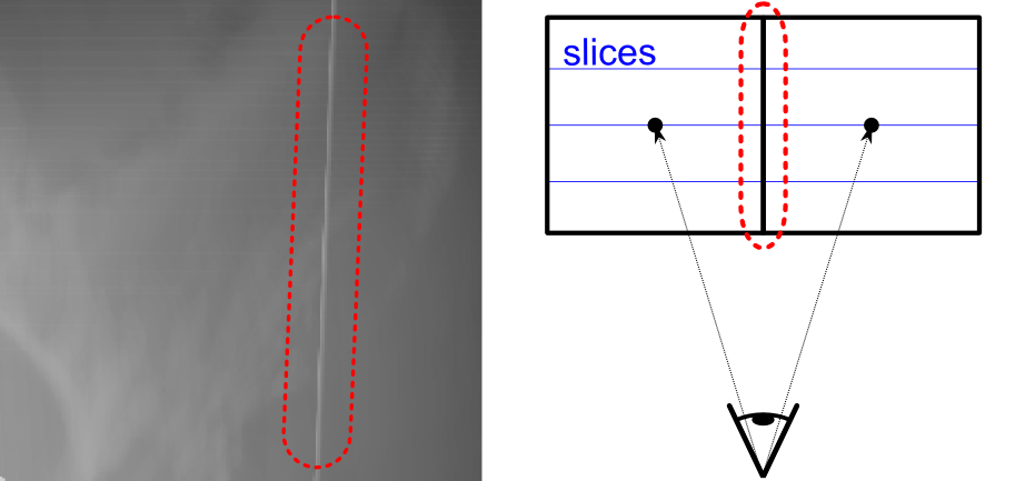
The solution is rather simple:
The other type of artifacts arises straight from the solution for the first one, depending on how the depth sorting is accomplished. Common implementations compute object distances by evaluating the distance to their centers. If this method was used here, we would observe the artifacts illustrated in the figure below when rendering grid cells of different sizes.

The term watershed in the picture above refers to an analogy: If the eye is located on the left side, than the left cell is considered closer, otherwise the right cell. The numbers refer to the (reverse) recognized depth order, i.e. the order of rendering the volumes. The watershed, computed from the center-distances, is perfectly fine for equally sized cells, but becomes wrong if one cell is smaller: Here the watershed is shifted to left of where it actually should be. The left cell is rendered first, because the right one is considered closer. This prevents the red-shaded area of the right cell from being rendered afterwards, because the depth test fails in this area.
The solution is to use a different distance measuring. Instead of computing the distances to the cell centers, we compute the actual distances to the cells. The depth-sorting implementation does this if an appropriate bounding box is set upon the geometry node. The helpers::VolumeGridHelper class configures such bounding boxes for you.
It is important to have an idea of how shaders access textures. For each texture that a shader is able to read from, it must have an uniform variable declared. It is in the responsibility of the CPU-side program to map such variables to texture units. The uniform variable will then reflect the texture that is currently bound to that unit. For geometry nodes that this stage processes, it looks for such geometry features that are from type base::ManagedTexture3D. It then queries the names of the uniform variables, that these textures shall be linked with, from the implementation.
There are four functions that must be implemented:
Furthermore, you might want to override renderPass. The default implementation invokes the volume rendering algorithm, as it is described above. It is a typical practice for implementations of this class to override this method s.t. it setups a different render target, than invokes the default implementation to render to this target, and finally to process the results by rendering them back to the actually configured output buffer. If alpha blending is used while doing the volume rendering to a dedicated buffer, than this step is frequently referred to as accumulation. For example, the MIPStage accumulates using the GL_MAX blend equation, or the DRRStage accumulates with GL_ADD to compute an integral.
Below are a few hints on how to implement the shader. Refer to the Integration into Materials section for hints on how to actually load the shader.
The vertex shader must declare the following GLSL version, uniform variables and vertex formats:
\code
#version 330
uniform mat4 tangentModel;
uniform mat4 modelViewProjection;

layout( location = 0 ) in vec4 inPosition;
\endcode
Furthermore, it must pass the model-space coordinates to the fragment shader, although the name of the variable used for this is arbitrary:
\code
out vec4 modelSpaceCoordinates;
\endcode
Most of the time you should be able to stick to this implementation:
\code
void main()
{
    modelSpaceCoordinates = tangentModel * inPosition;
    vec4 clippingCoordinates = modelViewProjection * modelSpaceCoordinates;
    gl_Position = clippingCoordinates;
}
\endcode
The fragment shader must declare the following GLSL version and uniform variables, along with a varying for the model-space coordinates, whose name must match the name used in the vertex shader:
\code
#version 330

uniform mat4 modelTexture;

in  vec4 modelSpaceCoordinates;
out vec4 gl_FragColor;
\endcode
The name of the color output variable gl_FragColor is arbitrary.
Below is the body of a typical implementation of the fragment shader, that writes the texture coordinates to the color output:
\code
void main()
{
    if( abs( modelSpaceCoordinates.x ) > 0.5 || abs( modelSpaceCoordinates.y ) > 0.5 || abs( modelSpaceCoordinates.z ) > 0.5 )
    {
        discard;
    }
    vec4 textureCoordinates = modelTexture * modelSpaceCoordinates;
    gl_FragColor = vec4( textureCoordinates.rgb, 1 );
}
\endcode
For a full example on how to implement the shader, refer to the files src/res/mip.vert and src/res/mip.frag. These should be self-explaining.
Definition at line 316 of file VolumeRenderingStage.h.
|
protectedpure virtual |
Acquires the shader from the base::ShaderManager, that is to be used for rendering the slices.
Implemented in Carna::presets::DRRStage, Carna::presets::DVRStage, Carna::presets::MaskRenderingStage, and Carna::presets::MIPStage.
|
protectedpure virtual |
Performs custom shader configuration on a per-pass level.
Implemented in Carna::presets::DRRStage, Carna::presets::DVRStage, Carna::presets::MaskRenderingStage, and Carna::presets::MIPStage.
|
protectedpure virtual |
Performs custom shader configuration on a per-volume level.
Implemented in Carna::presets::DRRStage, Carna::presets::DVRStage, Carna::presets::MaskRenderingStage, and Carna::presets::MIPStage.
|
protectedpure virtual |
Creates texture samplers for volume textures and uses registerSampler to assign them to the roles that they should be used with.
Implemented in Carna::presets::DRRStage, Carna::presets::DVRStage, Carna::presets::MaskRenderingStage, and Carna::presets::MIPStage.
|
protectedvirtual |
Loads video resources when rendering is triggered for the first time. Override this method if you need any additional resources to be loaded, but always call the base implementation.
+1. Reimplemented in Carna::presets::DRRStage, Carna::presets::DVRStage, and Carna::presets::MaskRenderingStage.
|
overrideprotectedvirtual |
Renders the renderable.
Implements Carna::base::GeometryStage< base::Renderable::BackToFront >.
|
overridevirtual |
Triggers the volume rendering.
Reimplemented from Carna::base::GeometryStage< base::Renderable::BackToFront >.
Reimplemented in Carna::presets::DRRStage, Carna::presets::DVRStage, Carna::presets::MaskRenderingStage, and Carna::presets::MIPStage.
| unsigned int Carna::presets::VolumeRenderingStage::sampleRate | ( | ) | const |
Tells number of slices to be rendered per segment.
sampleRate() >= 2 | void Carna::presets::VolumeRenderingStage::setSampleRate | ( | unsigned int | sampleRate | ) |
Sets number of slices to be rendered per segment.
sampleRate >= 2
|
protectedpure virtual |
Tells the name of the uniform variable, that the role texture is to be bound to. Use configureShader for custom shader configuration that goes beyond that.
Implemented in Carna::presets::DRRStage, Carna::presets::DVRStage, Carna::presets::MaskRenderingStage, and Carna::presets::MIPStage.
|
static |
Holds the default number of slices rendered per segment.
Definition at line 330 of file VolumeRenderingStage.h.
Documentation generated by Doxygen

